Pre-Slicer Diagnostic Standard

Read the Evidence Left by the Print

Start with the observed result. Compare recurring patterns, isolated defects, dimensional issues, surface changes, and functional consequences before deciding what to test next.

For hobbyists, makers, prototyping teams, small print farms, and design students.

Evidence First

Visual classification over random recalibration

Taxonomy

6 structured evaluation domains

Repeatability

Isolate hardware faults from process variation

Diagnostic Lens
Select Symptom Domain
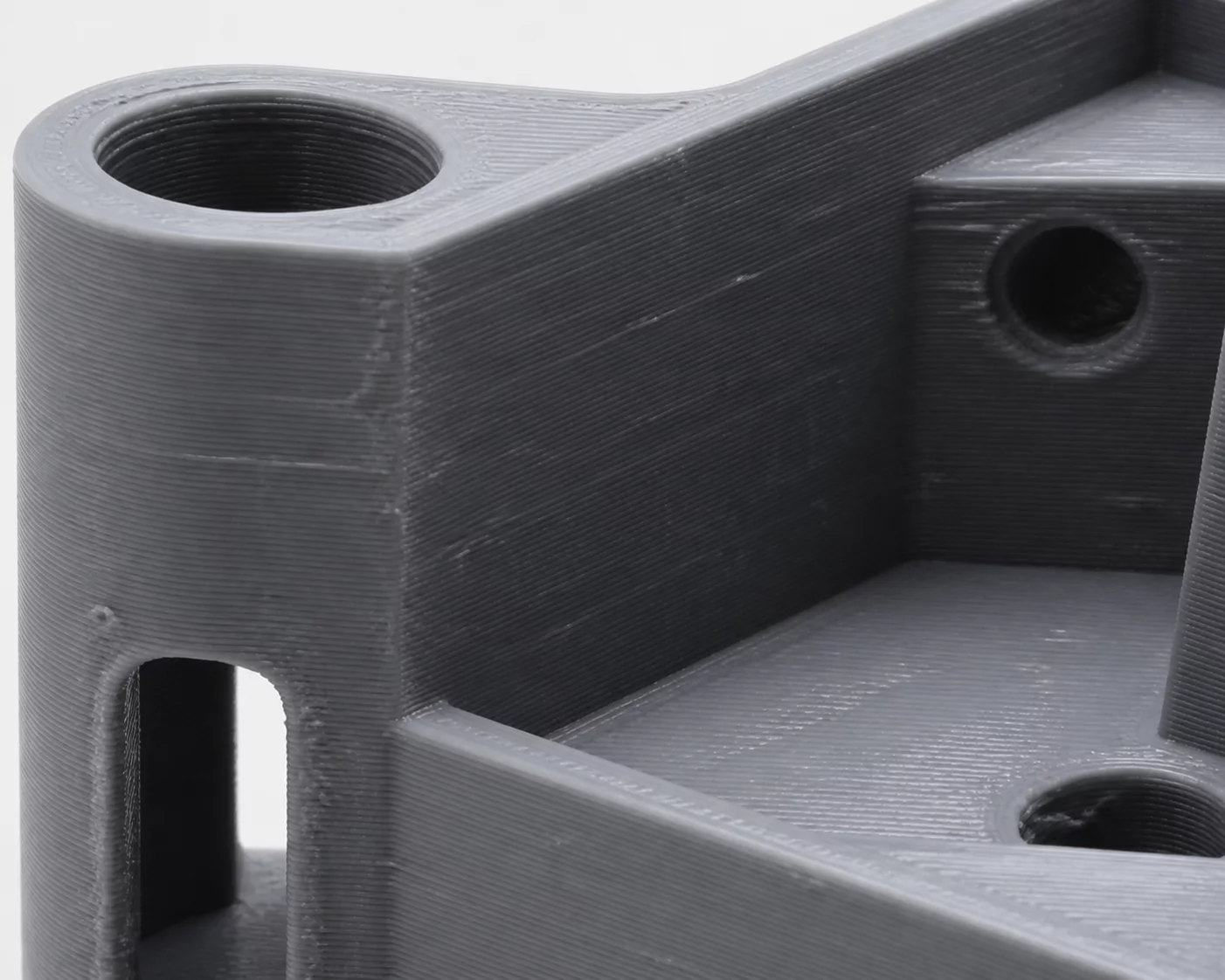
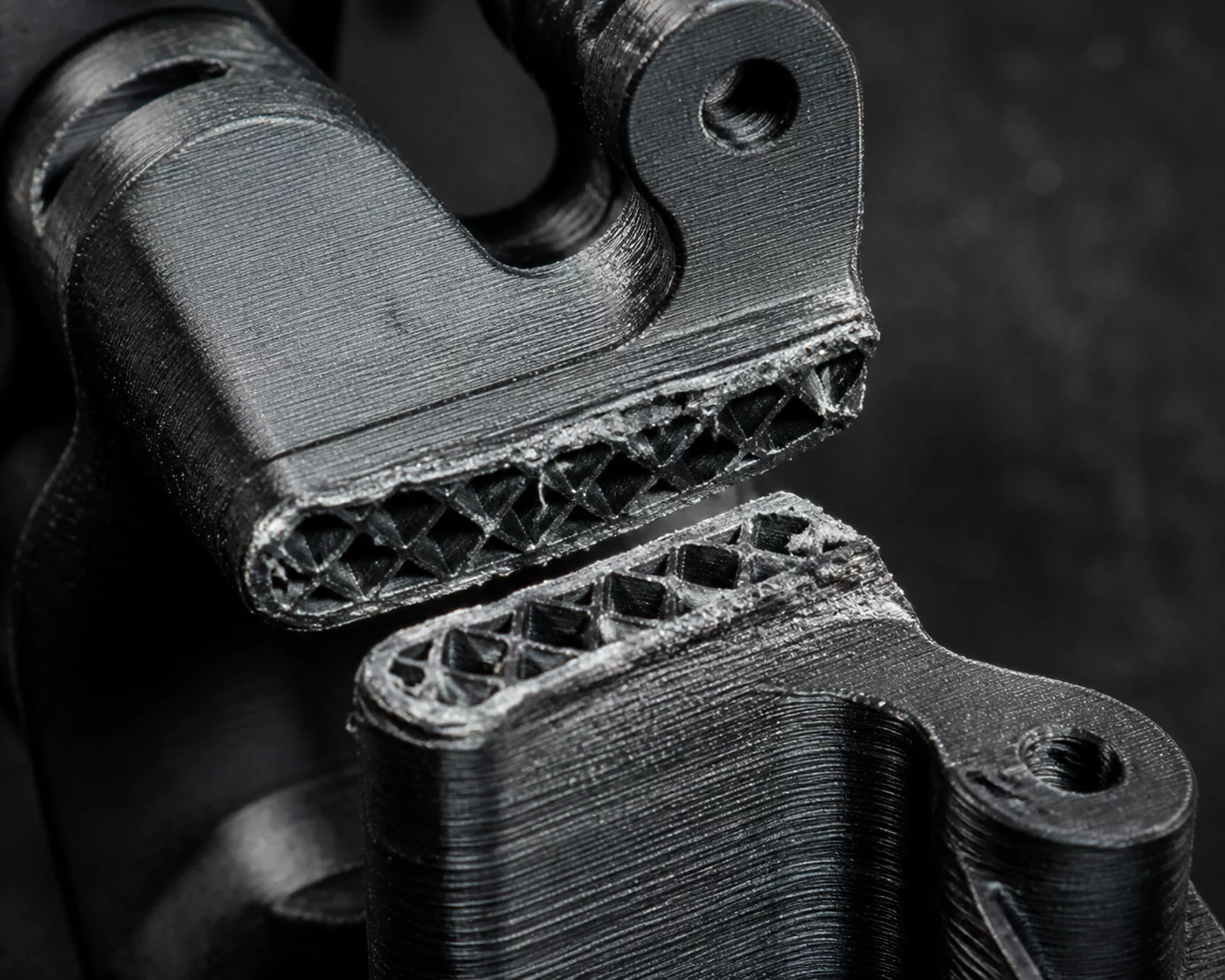
3D printed part showing irregular surface textures
Surface Evidence

Visual assessment of ridges, layer banding, and erratic extrusions before touching flow-rate sliders.

Read Surface Diagnostics
Diagnostic Infrastructure

Instruments & Technologies for Root-Cause Identification

Our diagnostic workflow applies systematic print failure analysis to isolate physical and slicing variables. By examining physical evidence under controlled magnification and toolpaths, we resolve 3D print defects before modifying slicer parameters, permanently eliminating repeated print problems.

G-Code Parsing

Volumetric Flow & Toolpath Simulation

Virtual layer-by-layer velocity verification. Identifies abrupt speed differentials and extrusion pressure spikes before sending files to the print bed.

ApplicationPrusaSlicer & Custom Parsers
Surface Optics

Macro Surface Inspection

High-resolution optical magnification for classifying micro-banding, under-extrusion voids, and seam scars under controlled raking light angles.

Application50x-200x Digital Microscopy
Geometry Check

Direct Dimensional Gauging

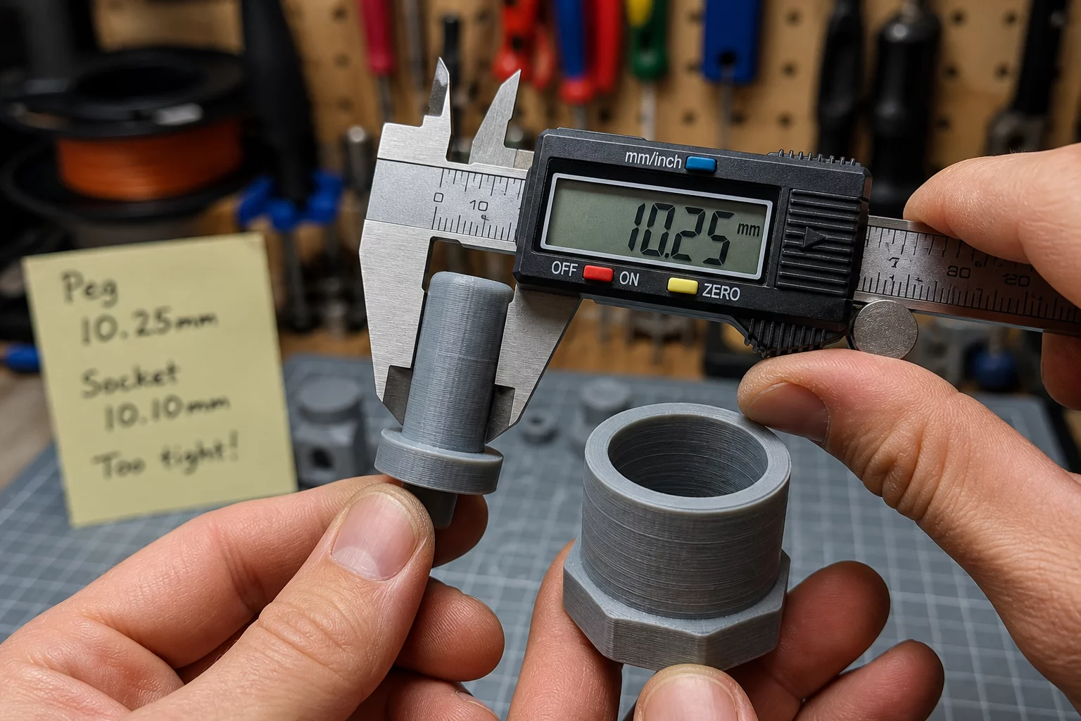
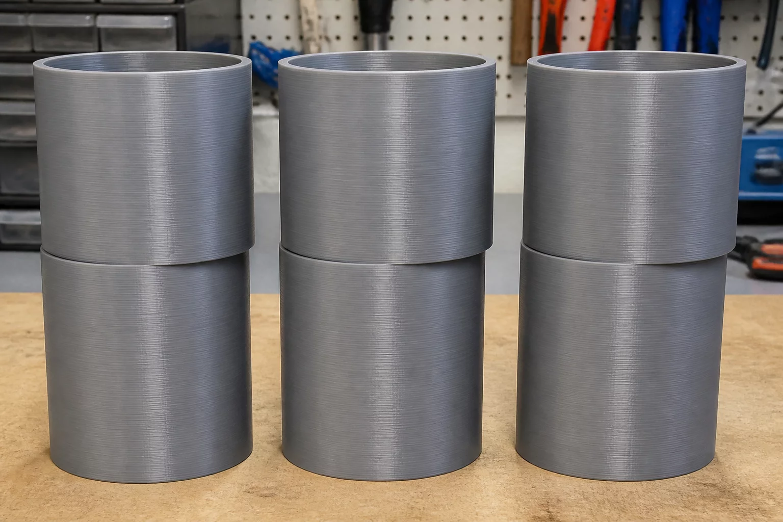
Calibrated micrometer probing of boreholes, horizontal expansions, and perpendicularity to separate shrinkage from mechanical skew.

ApplicationDigital Calipers & Feeler Gauges
Resonance Analysis

Input Shaping & Accelerometry

Capturing resonant mechanical frequencies along X and Y axes to diagnose ringing, ghosting, and belt tension discrepancies precisely.

ApplicationADXL345 Sensor Logging
Thermal Profiling

Chamber & Bed Thermal Mapping

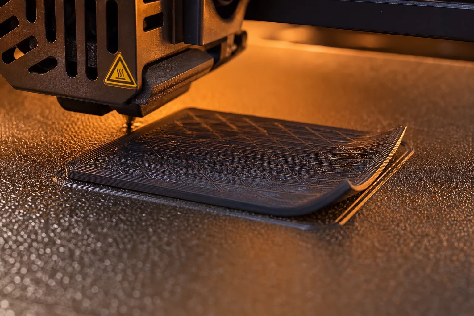
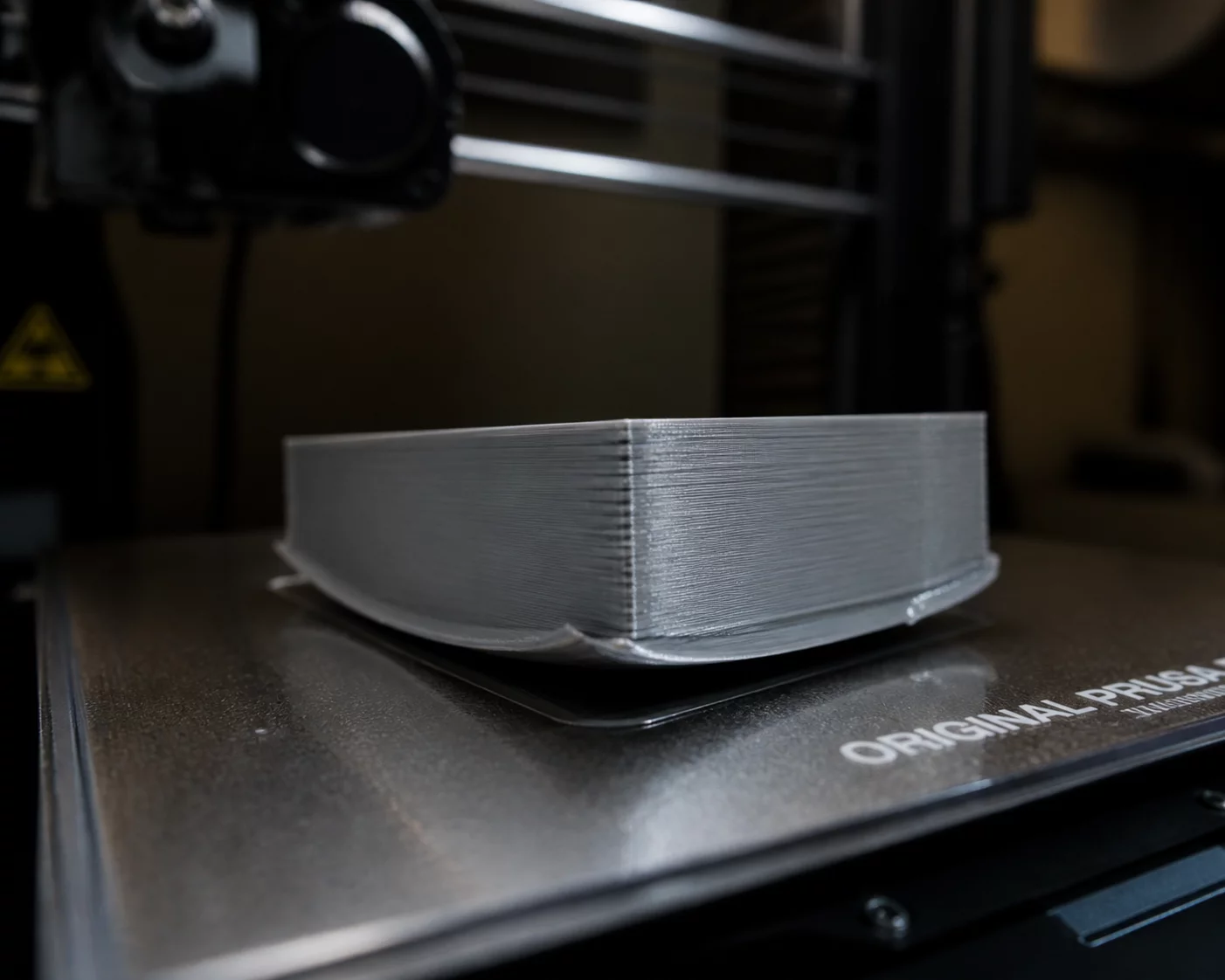
IR radiometry to verify heat dissipation and localized cool spots causing first-layer detachment, uneven crystallization, and severe corner lift.

ApplicationInfrared Thermography
Extrusion Ratio

Gravimetric Material Analysis

Precision mass comparisons between sliced model estimates and finished solid prints to quantify volumetric slip and filament diameter inconsistency.

Application0.001g Analytical Balances

Looking for detailed slicer workflow reviews?

Explore our specialized checklist for validating extrusion consistency and bridge thresholds.

Operational Drain Metric

The Hidden Cost of Diagnostic Delay in Workshop Operations

When 3D print defects arise, modifying slicer parameters by trial and error creates compounded losses. Without structured print failure analysis, repeated print problems consume machine availability, waste filament spools, and trap operators in endless diagnostic guesswork.

Current Failure & Diagnostic Audit

Enter your workshop failure baseline to evaluate the cumulative scale of unresolved print defects.

8 parts
6 hrs
4 hrs
120 g
Estimated Annual Tally
Cumulative Operational Drain
Lost Machine Time
576 hrs
Wasted print chamber availability / year
Scrapped Material
11.5 kg
Polymer converted into discard waste / year
Operator Guesswork
208 hrs
Spent on random slicer trial-and-error / year
Failed Runs Count
96 jobs
Interrupted or unserviceable assemblies / year

Continuing production without methodical defect classification allows unaddressed mechanical and slicing errors to compound over time.

Break the Failure Cycle
Identify root causes before adjusting slicer profiles.
Start Diagnostics

Equipment and Material Wear

Repeating abortive runs accelerates nozzle clogging, extruder gear degradation, and PEI sheet deterioration while turning premium spools into landfill debris.

Process Impact: Hardware Strain

Misguided Slicer Compensation

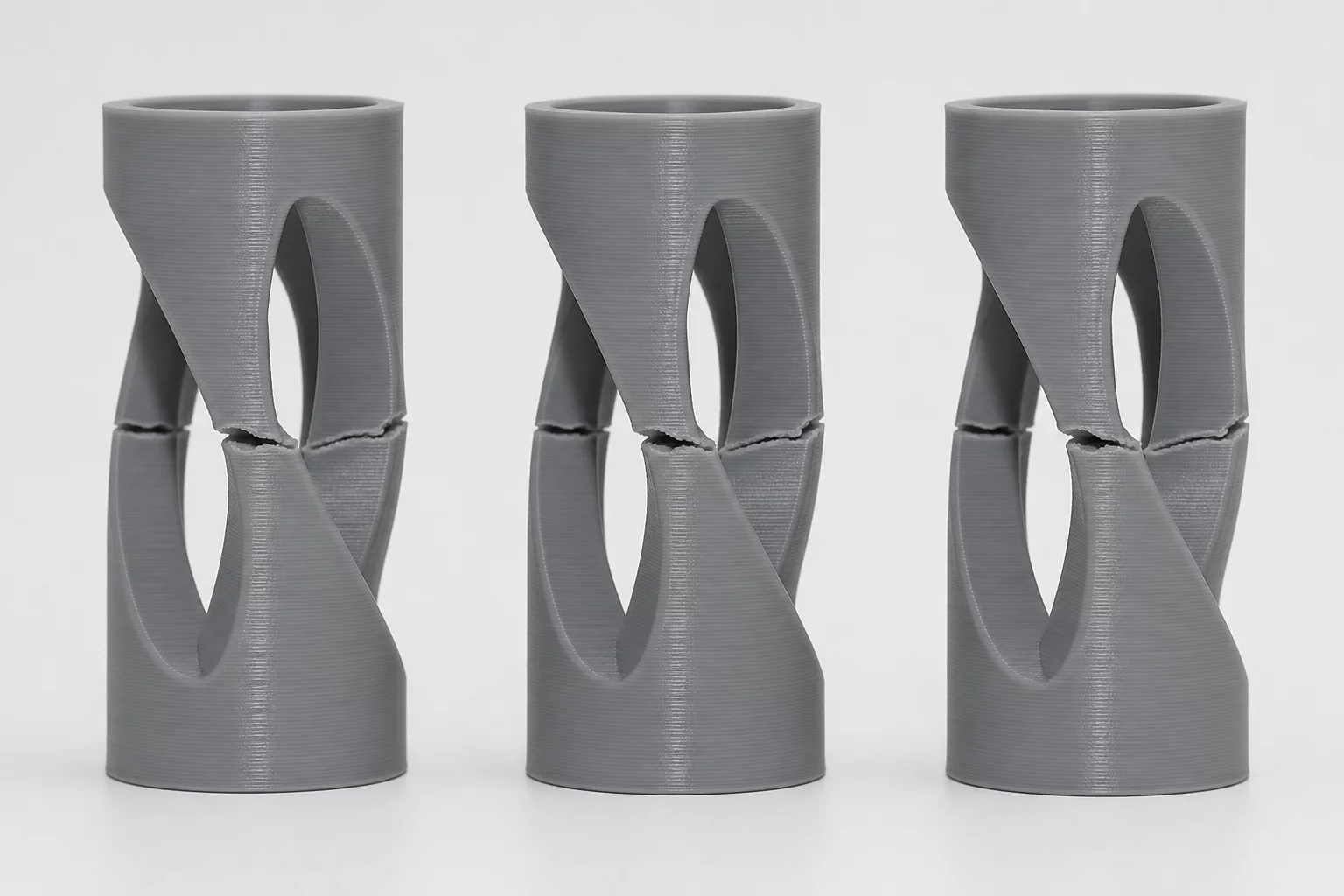
Modifying flow rates or cooling when hardware axes are loose masks actual hardware issues, resulting in fragile parts that break under slight mechanical load.

Process Impact: Latent Weakness

Capacity Bottlenecks

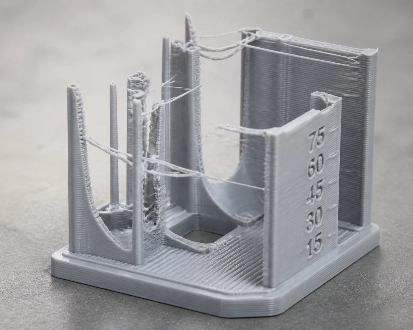
Every hour dedicated to clearing failed stringed towers or re-printing lifted corners directly cuts into real prototype iteration cycles and planned build schedules.

Process Impact: Throughput Stall
Process Methodology

Diagnostic Stages & Quality Checkpoints

Before adjusting a single parameter in your slicer, follow this structured four-stage evaluation pipeline to isolate physical root causes from configuration artifacts.

Initial ObservationClassification Gate 1.0

Inspect Layer Consistency and Surface Texture

Carefully document outer perimeters without removing supports or post-processing. Compare the physical artifact with lighting angled at 45 degrees to determine whether artifacts follow travel moves or periodic Z-axis intervals.

What the Diagnostician Observes:

  • Localized scarring, periodic banding, or micro-voids across identical Z-heights.
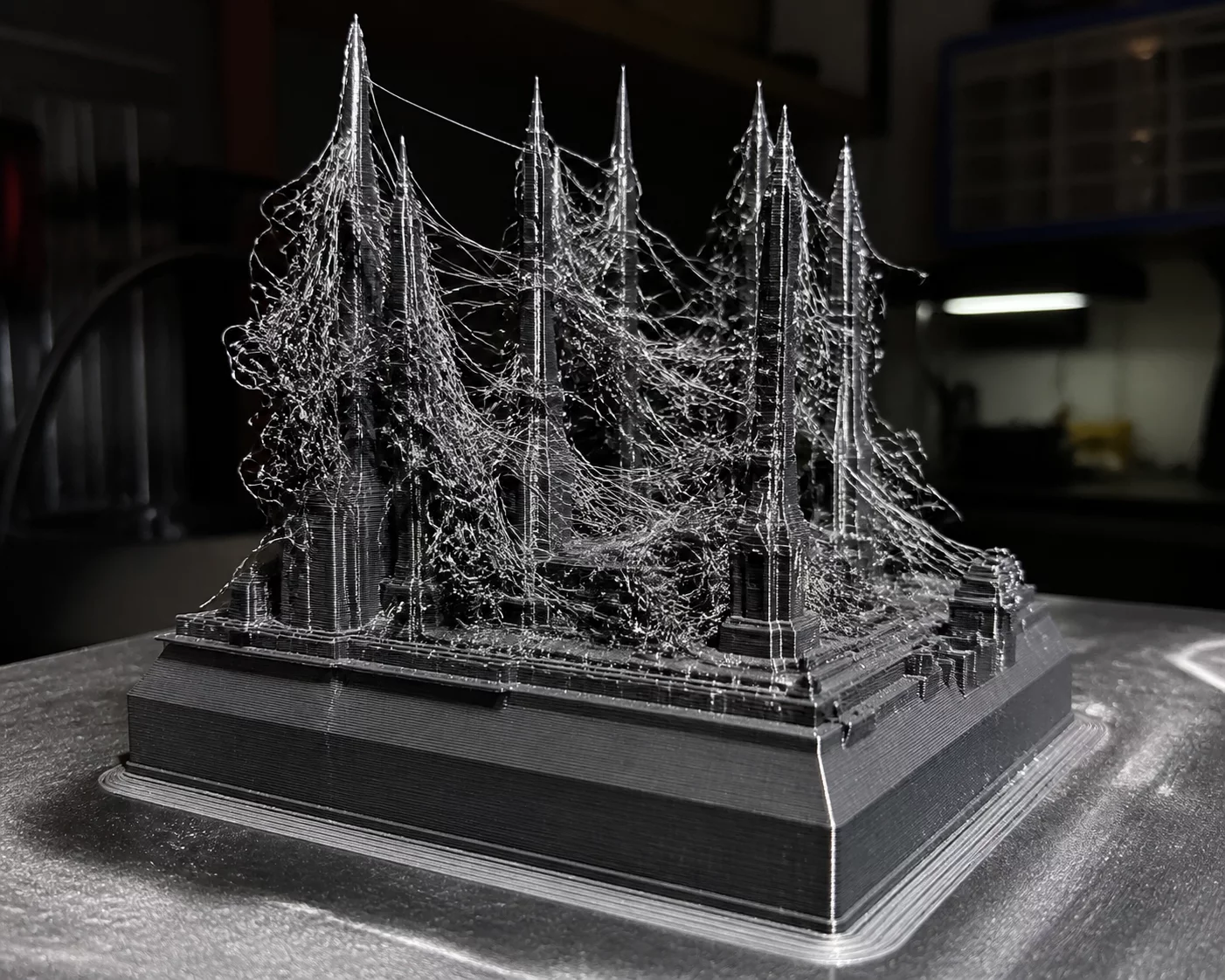
  • Whispering or spiderweb stringing spanning open travel vectors.
STAGE 01 CHECKPOINTS3 Verification Items
Artifact Unaltered
Part is untouched by sandpaper, heat guns, or solvent wash.
Build Orientation Marked
X, Y, and Z axes relative to the build plate coordinate system recorded.
Macro Photos Cataloged
High-contrast photos taken under directional side illumination.
Diagnostic Taxonomic Matrix

Physical Defect Classifications

Review surface anomalies, volumetric warping, and interface misfits against empirical evidence before modifying slicer profiles.

Looking for workflow-specific slicer outcome reviews? Consult our specialized guide for PrusaSlicer inspection parameters.

Slicer Review
Diagnostic Guides & Protocols

Field Troubleshooting Manuals

Systematic methodologies for print failure analysis. Learn to decode distinct 3D print defects and resolve repeated print problems with disciplined hardware and slicer verification.