Fit Evidence
Evaluating parts that printed successfully with clean exterior surfaces but stubbornly refuse to assemble, interlock, or satisfy specified slide tolerances.
Triage Checklist
- Preserve failed physical part without trimming.
- Record exact layer height and filament spool ID.
- Isolate hardware binding before modifying slicer flow.

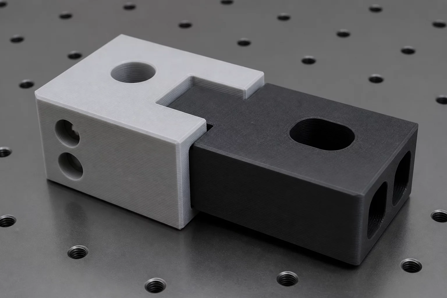
Figure 1.1: Physical extrusion manifestation recorded on standard test specimen.
Diagnostic Analysis & Visual Taxonomy
When additive components complete without layer shifts, warping, or visible stringing, technicians frequently mistake cosmetic beauty for dimensional truth. Fit evidence manifests at the boundary interfaces: dowel pins jam inside mating sockets, sliding dovetails bind midway through insertion, and precision screw holes measure between 0.20mm and 0.45mm undersized. These mechanical discrepancies originate from the physics of molten thermoplastic deposition, where extrusion bead rounding and cooling contraction conspire against sharp interior contours.
“A visually immaculate surface finish provides zero guarantee of interfacial clearance; polygon approximation and radial thermal contraction inevitably constrict interior bores unless compensated at the slicer boundary.”
The root mechanism lies in how slicing engines translate CAD geometry into toolpaths. Circular bores are approximated as chord segments rather than true arcs. During deposition, the extruded bead stretches along the chord string line, pulling inward toward the hole center. Combined with corner acceleration swelling on exterior perimeter loops, male geometries expand outward while female cavities contract inward, eliminating design clearances entirely.
Root Cause Verification Matrix
Primary Mechanical Origin
Interior bore chord shrinkage and toolpath polygonization pull the molten thermoplastic toward the cavity center, constricting circular hole diameters by 0.15mm to 0.35mm across default nozzle profiles.
Secondary Process / Thermal Factor
Corner over-extrusion from uncalibrated pressure advance combines with first-layer thermal elephant foot expansion, creating localized interface interference at the bottom and corners of the part.
Step-by-Step Verification Protocol
-
01.
Mechanical Kinematics Audit Measure external outer dimensions against CAD references with calibrated calipers. If outer walls measure nominal while inner holes measure undersized, rule out global belt scaling errors.
-
02.
Thermal & Extrusion Validation Print a single-wall hollow cube to confirm actual perimeter extrusion width matches the nominal slicer value before adjusting compensation offsets.
-
03.
Slicer Toolpath Alignment Apply X-Y Hole Compensation (+0.15mm) and X-Y Contour Compensation (-0.05mm) in the slicer profile, maintaining consistent flow rate across perimeter passes.
Case Observations & Peer Diagnoses
Verified workshop test runs and metallurgical logs
Submit Empirical Case Evidence
Documented physical findings contribute to the open failure taxonomy index.