
Functional Consequences
Determining when a cosmetic issue begins to impact the mechanical function of the part, compromising load capacity, structural cohesion, and dimensional life expectancy.
Triage Checklist
- Preserve failed physical part without trimming.
- Record exact layer height and filament spool ID.
- Isolate hardware binding before modifying slicer flow.
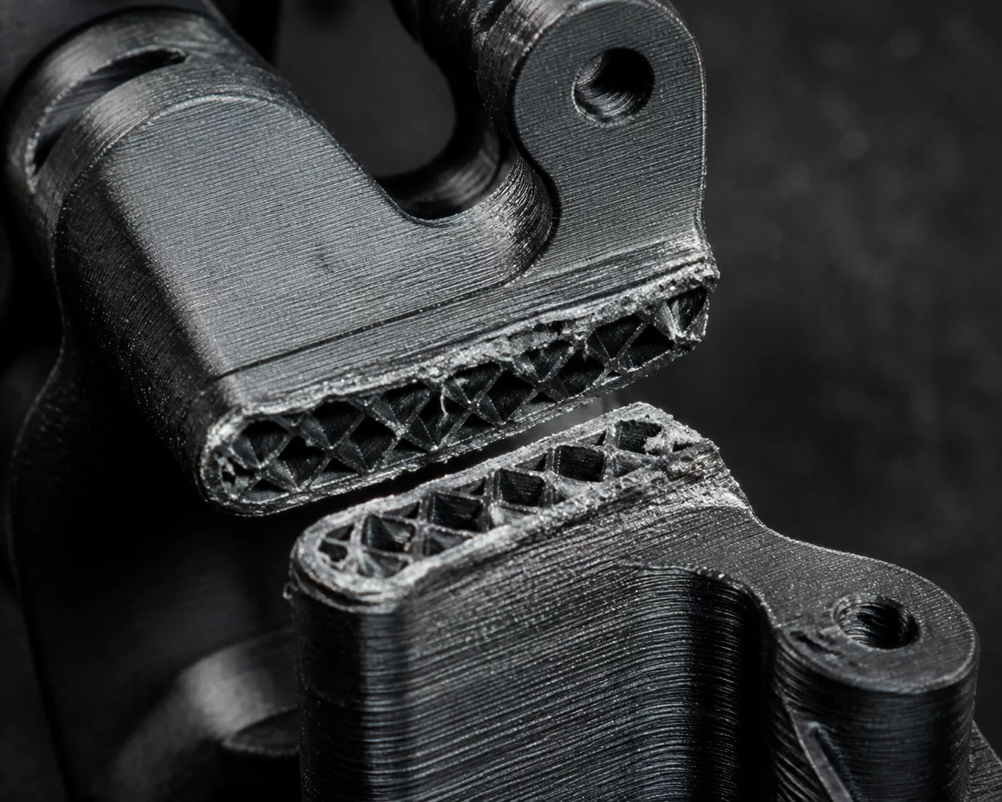
Figure 1.1: Physical fracture plane along an under-bonded layer interface in a functional bracket.
Diagnostic Analysis & Visual Taxonomy
In fused filament fabrication, the boundary separating a minor surface defect from a critical mechanical breakdown is defined by stress concentrations and interlayer weld efficiency. While faint outer surface ringing or a misaligned seam can often be tolerated on purely aesthetic enclosures, those identical patterns become severe stress concentrators when situated across tensile cross-sections. When microscopic voids form between adjacent extrusion beads, the effective load-bearing area shrinks dramatically, prompting premature delamination long before reaching the bulk material tensile yield limit.
A cosmetic line that merely refracts ambient light is benign, but an identical line accompanied by internal bead notch separation converts every cyclic vibration into rapid fatigue cleavage.
Inspecting functional failures requires distinguishing between bulk shear rupture and laminar separation. A brittle break across layer interfaces points directly to insufficient melt bonding, excessive cooling airflow, or print speeds that outrun the hotend volumetric melt capacity. In contrast, fractures that shear diagonally across solid infill lines demonstrate that the interlayer bond exceeded the tensile strength of the extruded plastic matrix itself. Establishing this difference determines whether corrective action belongs in thermal profile adjustments or structural geometry redesign.
Root Cause Verification Matrix
Primary Mechanical Origin
Interlayer bond starvation driven by insufficient extrusion temperature, excessive part cooling fan speed on engineering polymers, or hotend volumetric throughput throttling during high-speed perimeter runs.
Secondary Process / Thermal Factor
Infill-to-wall overlap deficit creating internal shear gaps, exacerbated by ambient chamber temperature fluctuations that induce anisotropic thermal contraction along sharp internal radii.
Step-by-Step Verification Protocol
-
01.
Mechanical Kinematics Audit Examine the fractured surface under 10x magnification to confirm whether failure occurred along a single layer plane (interlayer adhesion defect) or diagonal infill tracks (overload failure).
-
02.
Thermal & Extrusion Validation Run a standardized single-wall cylinder test print with temperature steps (+5°C increments) and reduce part cooling by 20% to quantify bead weld fusion strength under manual torque loading.
-
03.
Slicer Toolpath Alignment Increase wall perimeter loops to at least 4 lines, raise infill overlap percentage to 25–30%, and reorient load-bearing tensile vectors parallel to the XY plane.
Case Observations & Peer Diagnoses
Verified workshop test runs and metallurgical logs
Submit Empirical Case Evidence
Documented physical findings contribute to the open failure taxonomy index.