Systematic Print Failure Analysis & Evidence Classification
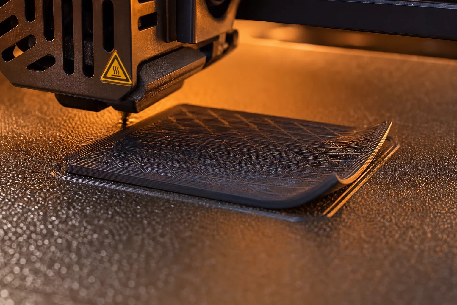
A systematic print failure analysis reveals that asymmetric corner lifting rarely stems from incorrect global build plate temperatures. When three corners maintain solid bond strength while one corner pulls upward, the defect points directly toward localized environmental asymmetries or localized bed defects rather than improper filament profile configurations.
Observing recurring 3D print defects of this type prevents unnecessary global slicer tampering. Changing the first layer extrusion multiplier or overall bed temperature across the whole plate often creates elephant foot defects elsewhere without fixing the underlying localized detachment trigger.
«Asymmetric corner warping is predominantly driven by localized convective cooling drafts or fingerprint residue rather than uniform thermal bed inaccuracy.»
Physical Symptom Investigation
Examine the bottom face of the peeled corner under a directional light source. A pristine, mirror-smooth separation indicates loss of chemical adhesion, commonly triggered by finger oils or degraded PEI coating. Conversely, if the separated corner displays stretched filament strands or broken perimeter loops, the cause lies in excessive tensile shrinkage pull overcoming a normal adhesive bond.
- Verify localized bed heater traces using an infrared thermometer to detect regional cold spots.
- Inspect auxiliary cooling fan orientation to confirm that the blower is not channeling concentrated ambient air directly at one quadrant.
- Check automatic bed leveling mesh variance to ensure first layer squish does not exceed 0.08mm deviation at that corner.
Case Diagnoses & Community Logs
Peer-reviewed diagnostic notesI always struggle with corner lifting on broad structural bases. I noticed the front-left corner constantly popped off around layer 20 while the rest of the print stayed completely flat.
«Rotating the model 45 degrees confirmed that the defect was localized to the front fan intake path on my enclosure.»
Submit Diagnostic Observation
Document print failure analysis metrics from your test specimens.