Systematic Print Failure Analysis & Evidence Classification
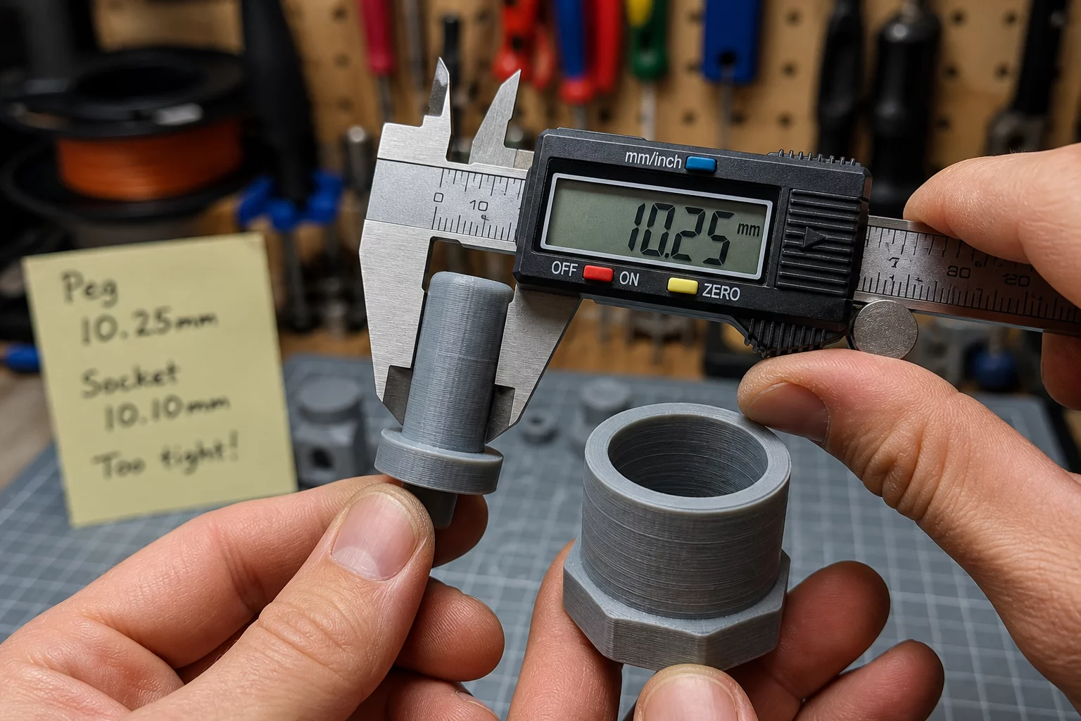
Aesthetic perfection during visual inspection frequently conceals underlying geometric drift. When conducting rigorous print failure analysis, technicians must distinguish between cosmetic surface quality and metrological accuracy. Understanding how molten thermoplastic contracts inward around circular toolpaths isolates 3D print defects before uncalibrated flow overrides corrupt the rest of the slice.
«Surface gloss and flawless layer consistency do not guarantee geometric adherence; always verify hole shrinkage, elephant foot flare, and polygon cord error with digital calipers.»
Physical Symptom Investigation
The specimen presents smooth outer walls, crisp top solid infill, and minimal layer banding. However, mating components fail to engage. Cylindrical shafts bind in receiving cavities, dovetail sliders experience severe mechanical lockup halfway through travel, and M3 hardware refuses to seat without thread-stripping force. The root cause lies in radial polymer tension pulling inner hole boundaries toward the centroid during extrusion, combined with discrete mesh facet approximations.
- Measure outer boundary dimensions against internal bore diameters to calculate perimeter bias.
- Inspect the first three base layers for elephant's foot flare obstructing insertion chamfers.
- Validate slicing tolerance mode (Exclusive vs Middle) in the slicer perimeter engine.
Case Diagnoses & Community Logs
Peer-reviewed diagnostic notesDimensional accuracy is tricky.
«The outer shell looked completely pristine, but internal bore undersizing made bearing press-fits impossible until hole compensation was applied.»
Submit Diagnostic Observation
Document print failure analysis metrics from your test specimens.