Repeatability
Distinguishing between an isolated extrusion defect and a repeating mechanical or thermal pattern across successive production runs.
Triage Checklist
- Preserve failed physical part without trimming.
- Record exact layer height and filament spool ID.
- Isolate hardware binding before modifying slicer flow.
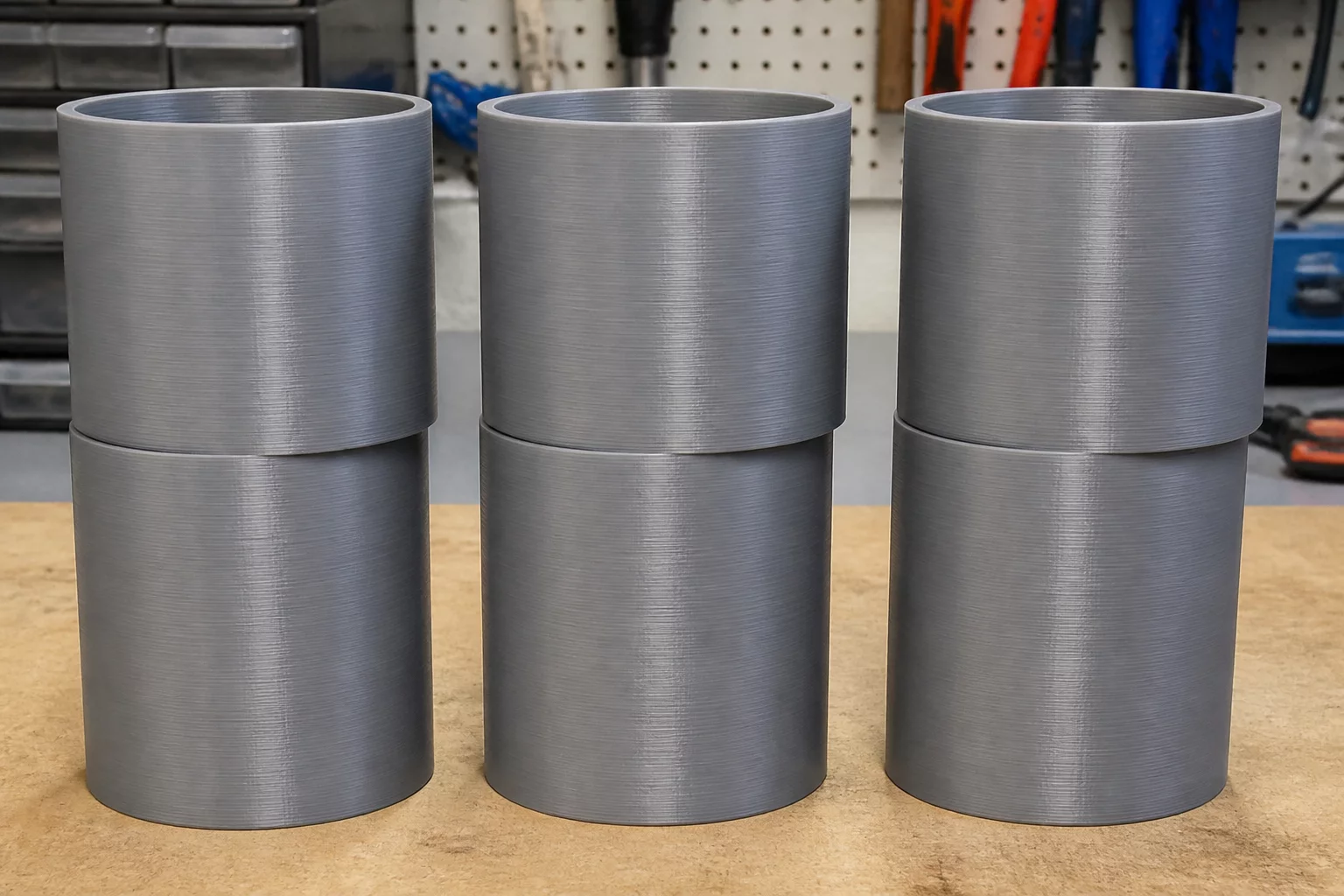
Figure 1.1: Physical extrusion manifestation recorded on standard test specimen.
Diagnostic Analysis & Visual Taxonomy
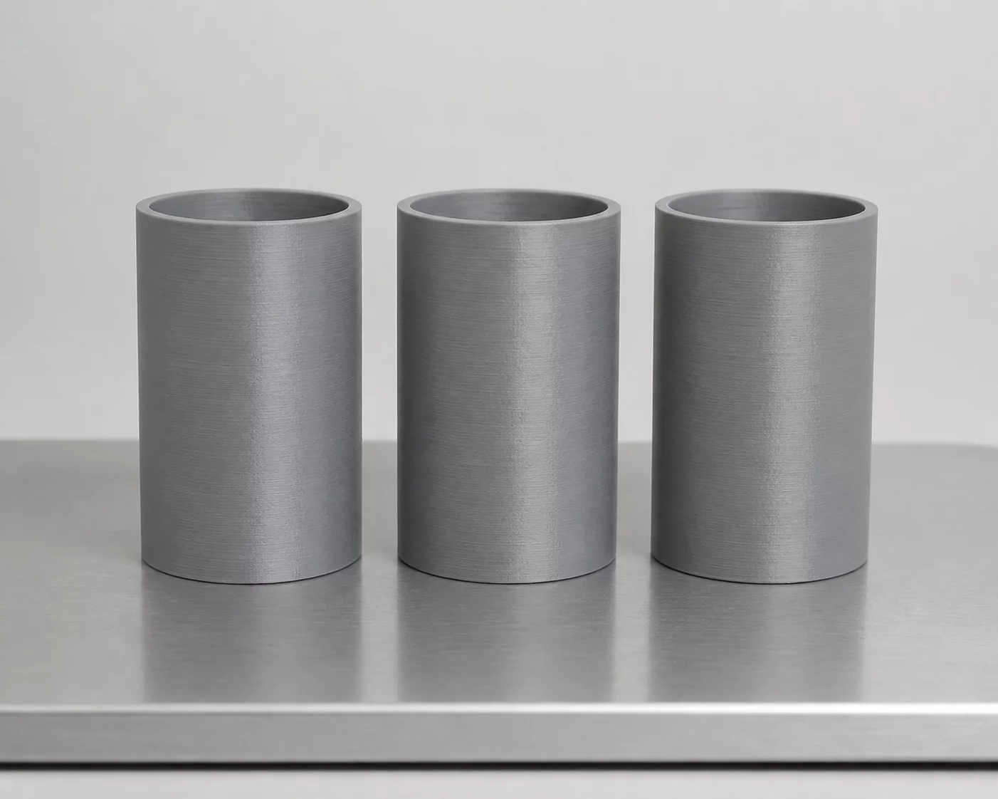
Identifying whether an imperfection represents a singular event or a structural pattern requires structured batch comparison. When three successive cylinders display an identical horizontal line at exactly 42.4mm, the problem originates inside the physical drive mechanics or the toolpath instructions rather than from raw filament variance. Isolated defects stem from random contamination, draft gusts, or localized spool knots, whereas repeating anomalies point directly to machine geometry and synchronized kinematic wear.
“A flaw that repeats at identical vertical coordinates across three consecutive prints is never a random slice anomaly; it is a direct mechanical fingerprint of the motion system.”
Operators often waste substantial production time altering extrusion flow rates and temperatures when confronted with repeatable surface bands. Inspecting the pitch distance between repeating ridges reveals the root mechanism: an 8mm cycle reflects a standard lead screw lead, while a 2mm periodicity mirrors GT2 belt tooth engagement. Differentiating these signatures allows precise hardware remediation before touching slicer variables.
Root Cause Verification Matrix
Primary Mechanical Origin
Periodic mechanical runout, lead screw binding, eccentric drive pulleys, or persistent toolpath coordinates reproducing synchronized layer displacement.
Secondary Process / Thermal Factor
Cyclic bang-bang bed heating oscillations creating synchronized thermal expansion waves or periodic cooling fan voltage sags during tool transitions.
Step-by-Step Verification Protocol
-
01.
Mechanical Kinematics Audit Measure the exact Z-height distance between recurring ridges with digital vernier calipers to match against lead screw thread pitch or belt tooth intervals.
-
02.
Thermal & Extrusion Validation Reposition the model to a different quadrant of the build plate; if the defect shifts position relative to the bed, isolate axis rail contamination.
-
03.
Slicer Toolpath Alignment Re-slice the object with a modified layer height and altered seam placement to distinguish kinematic binding from toolpath geometry bugs.
Case Observations & Peer Diagnoses
Verified workshop test runs and metallurgical logs
Submit Empirical Case Evidence
Documented physical findings contribute to the open failure taxonomy index.
No diagnostic case logs recorded yet. Be the first to submit empirical findings for this defect pattern.