Surface Evidence
Systematic physical identification of visible banding, ringing ripples, top-surface scarring, and localized texture shifts on finished thermoplastic prints.
Triage Checklist
- Preserve failed physical part without trimming.
- Record exact layer height and filament spool ID.
- Isolate hardware binding before modifying slicer flow.
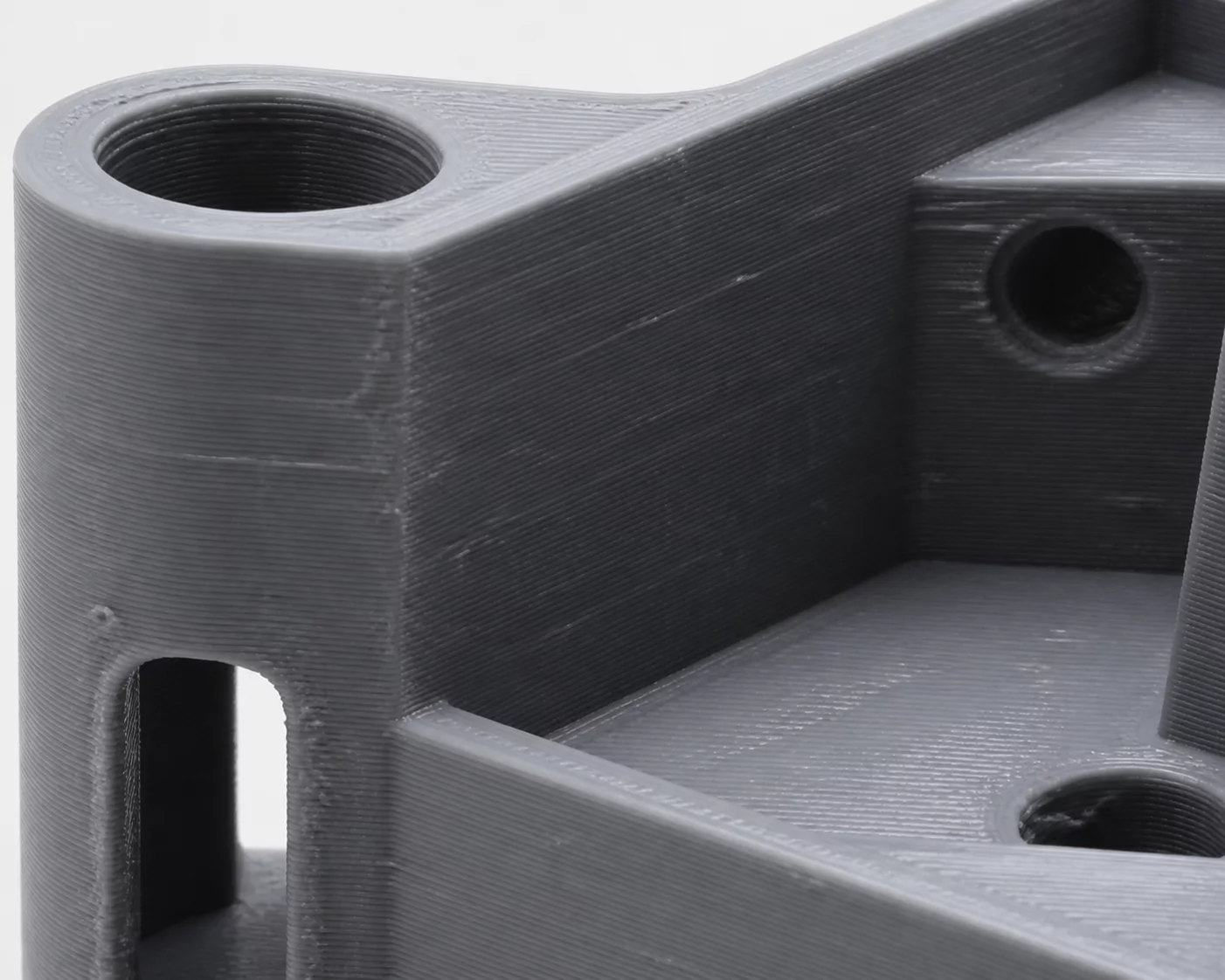
Figure 1.1: Physical extrusion manifestation recorded on standard test specimen.
Diagnostic Analysis & Visual Taxonomy
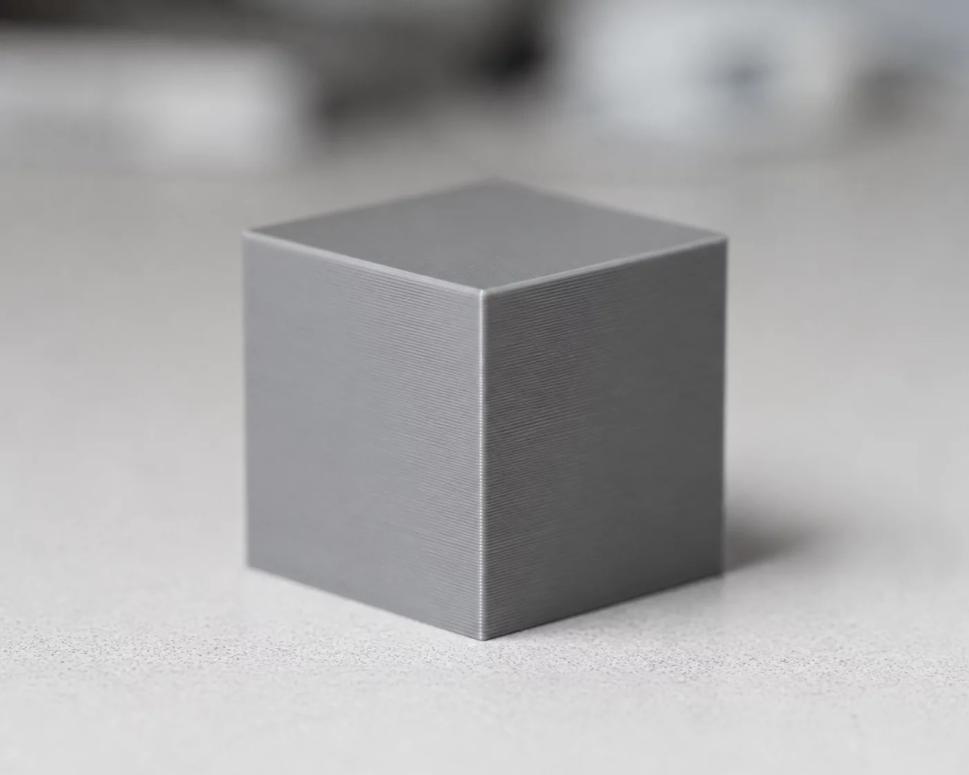
Analysis of visible lines, texture changes, scars, and irregular surfaces on 3D printed parts begins with isolating physical surface traits from internal structural failures. Surface irregularities manifest when molten polymer deposition is disturbed by mechanical vibrations, uneven thermal contraction, or feed-rate inconsistencies. Observing the exact orientation, frequency, and height distribution of layer ridges allows technicians to separate slicer configuration oversights from physical kinematic resonance.
Periodic surface waves along perimeter walls indicate kinematic vibration or lead screw binding, whereas stochastic roughness points directly to filament moisture or melt-zone thermal fluctuations.
High-speed perimeter motion frequently triggers phantom ripples known as ghosting or ringing near sharp directional corners. When print acceleration exceeds the rigidity of the gantry or belt tension tolerances, kinetic energy dissipates into the extruded wall. Inspecting surface ridges under angled side illumination highlights whether the deviation follows corner proximity or repeats across uniform geometric intervals regardless of travel direction.
Root Cause Verification Matrix
Primary Mechanical Origin
Mechanical resonance from improper belt tensioning, loose toolhead carriage bearings, or lead screw wobble causing physical displacement during extrusion passes.
Secondary Process / Thermal Factor
Fluctuations in melt-zone temperature, filament diameter tolerance variations (>0.03mm), or sub-optimal cooling airflow creating uneven bead solidification.
Step-by-Step Verification Protocol
-
01.
Mechanical Kinematics Audit Inspect belt tension with a frequency analyzer (target 110–140 Hz across axis spans), verify drive pulley grub screws, and confirm linear guide carriages demonstrate zero axial play.
-
02.
Thermal & Extrusion Validation Run a PID hotend auto-tune at target extrusion temperatures with cooling fan at 100%, and dry the polymer spool for 6 hours to eliminate moisture-induced micro-bursting.
-
03.
Slicer Toolpath Alignment Adjust outer wall acceleration limits, align the Z-seam to internal corners, and set perimeter speeds to establish consistent volumetric flow across adjacent layers.
Case Observations & Peer Diagnoses
Verified workshop test runs and metallurgical logs
Submit Empirical Case Evidence
Documented physical findings contribute to the open failure taxonomy index.