Geometry Evidence
Diagnostic guide for warping, distortion, and unexpected dimensions in prints.
Triage Checklist
- Preserve failed physical part without trimming.
- Record exact layer height and filament spool ID.
- Isolate hardware binding before modifying slicer flow.
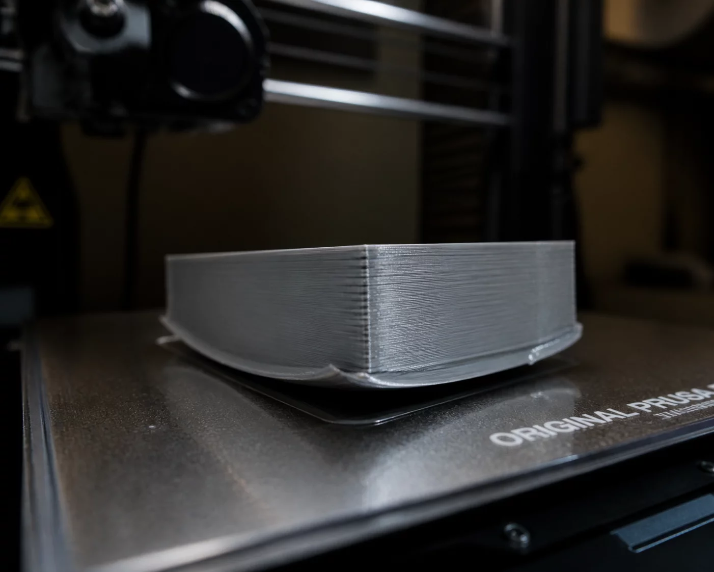
Figure 1.1: Physical extrusion manifestation recorded on standard test specimen.
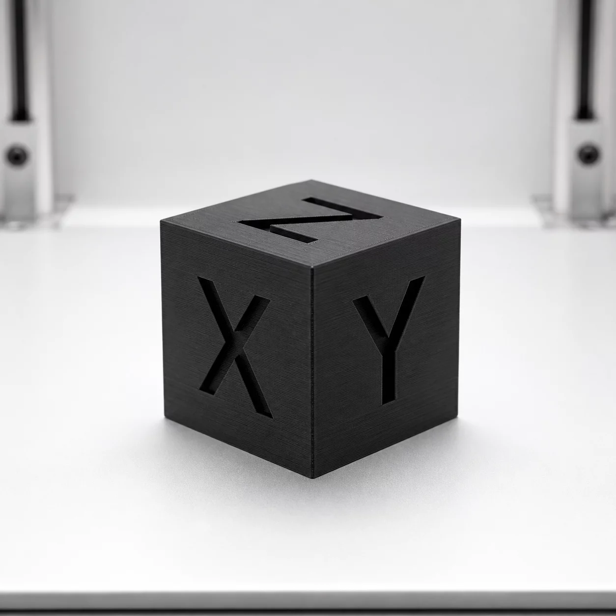
Diagnostic Analysis & Visual Taxonomy
Geometric deviation appears when printed parts fail to maintain their intended volumetric proportions, angles, or planar boundaries. Unlike subtle micro-texture defects, geometry errors directly alter mating surfaces, squareness, and overall envelope tolerances. A lifted bottom corner or curved baseplate profile indicates uneven volumetric shrinkage as hot extruded plastic cools against a cooler bed surface.
«Thermal stress builds continuously across successive layers. When adhesive surface forces drop below internal material contraction forces, geometric distortion becomes inevitable.»
Diagnostic inspection must separate thermal shrinkage from mechanical gantry skew. If vertical walls tilt consistently along an axis regardless of print orientation, mechanical perpendicularity requires alignment. When distortion concentrates near sharp corners or thin base tabs, local cooling dynamics and bed contact temperatures represent the primary variables.
Root Cause Verification Matrix
Primary Mechanical Origin
Frame non-orthogonality, loose gantry pulley setscrews, uneven lead screw pitch, or non-parallel linear guide rails causing skew and dimensional drift across X, Y, and Z axes.
Secondary Process / Thermal Factor
Differential thermal contraction caused by premature auxiliary cooling, unheated chamber drafts, or insufficient build plate surface temperature relative to glass transition points.
Step-by-Step Verification Protocol
-
01.
Mechanical Kinematics Audit Measure gantry squareness with a machinist square and verify belt tension equalization across parallel core loops.
-
02.
Thermal & Extrusion Validation Map heated bed thermal gradient with contact sensors and seal the enclosure to eliminate ambient air velocity fluctuations.
-
03.
Slicer Toolpath Alignment Inspect first-layer expansion settings, brim width geometry, and corner acceleration parameters inside the slicer toolpath preview.
Case Observations & Peer Diagnoses
Verified workshop test runs and metallurgical logs
Submit Empirical Case Evidence
Documented physical findings contribute to the open failure taxonomy index.