Feature Evidence
Examining failures in thin walls, holes, bridges, and small details. A systematic approach to differentiating between thermal dissipation collapse, kinematic deceleration artifacts, and volumetric limits.
Triage Checklist
- Preserve failed physical part without trimming.
- Record exact layer height and filament spool ID.
- Isolate hardware binding before modifying slicer flow.
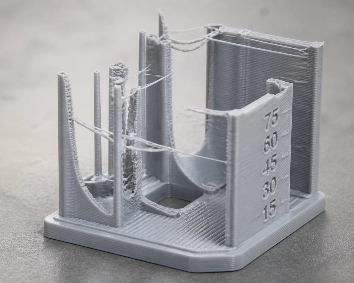
Figure 1.1: Physical extrusion manifestation recorded on standard test specimen.
Diagnostic Analysis & Visual Taxonomy
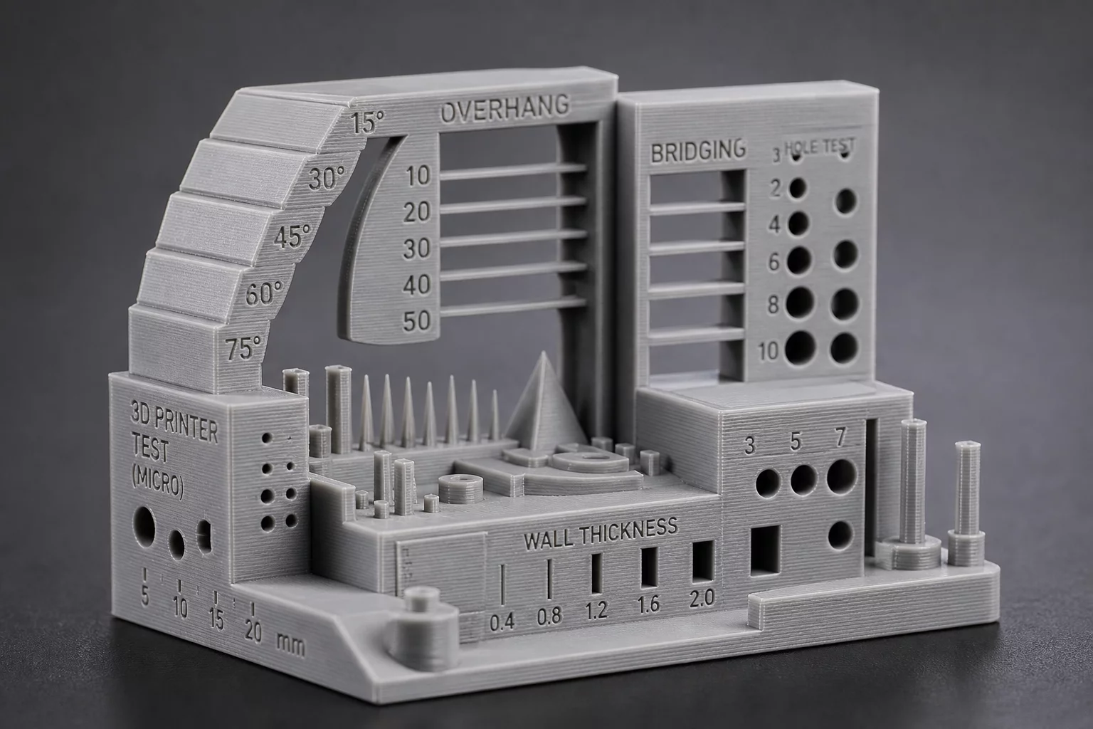
Micro-scale features in additive manufacturing operate right at the thermal edge of thermoplastic extrusion. When an extruder navigates narrow thin-walled ribs, sharp spires, or unsupported bridging spans, the material remains in a semi-molten state far longer than it does across heavy solid infill. Without balanced layer dwell time, fresh plastic is deposited onto a hot, compliant substrate, causing thin perimeters to curl upward and bridging strands to sag under gravity.
Thin features collapse when heat accumulation outpaces convective dissipation. Resolving delicate geometry failures requires isolating cooling air directionality and pressure advance before changing global extrusion multipliers.
In small horizontal holes and pin clearance slots, the centripetal pull of cooling plastic naturally constricts internal diameters. When technicians observe constricted holes alongside degraded overhang bridges, they frequently misdiagnose the symptom as global over-extrusion. Reducing overall flow rate starves solid structural regions while leaving the underlying cooling inadequacy and perimeter path dynamics unresolved.
Root Cause Verification Matrix
Primary Mechanical Origin
Inadequate part cooling fan duct orientation and thermal pooling on fast layer cycle times, leading to perimeter deformation and droop across unsupported spans.
Secondary Process / Thermal Factor
Uncompensated pressure build-up during corner decelerations causing localized perimeter widening, hole perimeter contraction, and incomplete bridge anchor bonds.
Step-by-Step Verification Protocol
-
01.
Mechanical Kinematics Audit Inspect the printhead cooling shroud for clogs or physical misalignment, and confirm that hotend thermistor readings remain stable under active airflow.
-
02.
Thermal & Extrusion Validation Print an incremental overhang and bridge temperature tower to determine the exact freezing point where thermoplastic bonds reliably without drooping.
-
03.
Slicer Toolpath Alignment Set minimum layer cooling thresholds to at least 8–12 seconds, enable bridge flow reduction (0.85–0.90), and verify hole horizontal expansion offsets.
Case Observations & Peer Diagnoses
Verified workshop test runs and metallurgical logs
Submit Empirical Case Evidence
Documented physical findings contribute to the open failure taxonomy index.