
Systematic Print Failure Analysis & Evidence Classification
Addressing repeated print problems requires rigorous classification of physical symptoms prior to random calibration changes. Understanding whether a defect is tied to thermal gradient shifts, kinematic backlash, or geometry orientation prevents compounding variable errors.
«Never alter global slicer extrusion or speed profiles when a failure occurs randomly across identical runs. Transient errors demand mechanical feed verification and environmental boundary control before revising stable toolpaths.»
Physical Symptom Investigation
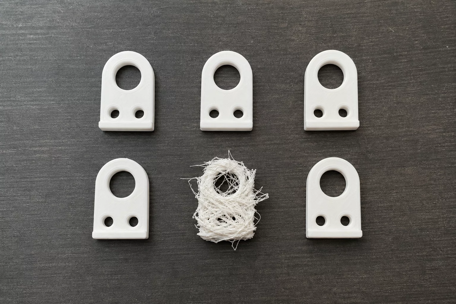
A single failed part nestled inside a succession of pristine units points to stochastic mechanical friction or momentary environmental fluctuations rather than permanent firmware errors. When five consecutive objects exhibit nominal wall thickness, sharp corners, and smooth surfaces while one sample experiences severe under-extrusion or mid-body delamination, the physical evidence indicates a temporary disruption in the material delivery chain.
- Inspect filament spool winding for temporary snagging, crossed strands, or excessive friction against spool holder flanges.
- Audit hotend temperature logs for brief thermal fluctuations exceeding 5°C caused by room airflow or cooling fan anomalies.
- Examine extruder drive gears for sporadic tooth clogging caused by accumulated filament debris slipping under peak retractions.
Case Diagnoses & Community Logs
Peer-reviewed diagnostic notesNo diagnostic comments logged yet. This could be your first comment.
Submit Diagnostic Observation
Document print failure analysis metrics from your test specimens.